Durham’s transformation from a tobacco and textile hub into a center for technology and medicine has reshaped its underground landscape as much as its skyline. The city sits squarely in the Piedmont physiographic province, where the bedrock is buried under a thick mantle of residual soil and partially weathered rock known as saprolite. This material behaves somewhere between soil and rock, holding steep temporary cuts well in dry conditions but degrading rapidly when exposed to water or vibration. Designing anchors here requires more than textbook pullout capacity equations; it demands an understanding of how saprolite loses cohesion at the interface between weathered and competent rock. The geotechnical team working in Durham routinely encounters micaceous silt zones within the saprolite that reduce grout-to-ground bond stress by as much as 30 percent compared to values predicted from SPT blow counts alone. For projects near the Eno River or in the Southpoint area, where groundwater is often perched within the weathered profile, the anchor design must also account for fluctuating hydrostatic pressures that alter the active earth pressure distribution behind a shoring wall. A thorough subsurface investigation with borings and in-situ testing becomes the foundation for every anchor load test program.
In Durham’s saprolite, anchor bond stress can vary by a factor of three within a single borehole, making sacrificial proof testing essential before production drilling begins.
Local considerations
Anchor design outcomes in Durham can differ dramatically between the relatively uniform saprolite of the western Research Triangle Park area and the alluvial deposits near the Eno River corridor in the north. In the RTP zone, where the Fiske regolith is deep and homogeneous, anchor capacities tend to be predictable and construction risks lower, though the presence of mica-rich horizons still demands conservative bond stress assumptions. Along the Eno River, however, the soil profile shifts to interbedded alluvial sands, silts, and gravels with groundwater within 8 feet of the surface. Here, passive anchors installed in granular materials without post-tensioning can experience excessive movement before mobilizing full resistance, potentially compromising adjacent utilities or pavement. An active anchor system with a locked-off load equal to 70 percent of design load becomes the preferred solution to limit deformation. The risk of anchor creep in these saturated alluvial soils increases during the winter and spring months when the water table rises, requiring a monitoring program with load cells on at least 10 percent of production anchors. Without this verification, a shoring wall can slowly rotate outward, exceeding serviceability limits and triggering costly repairs to nearby infrastructure.
Quick answers
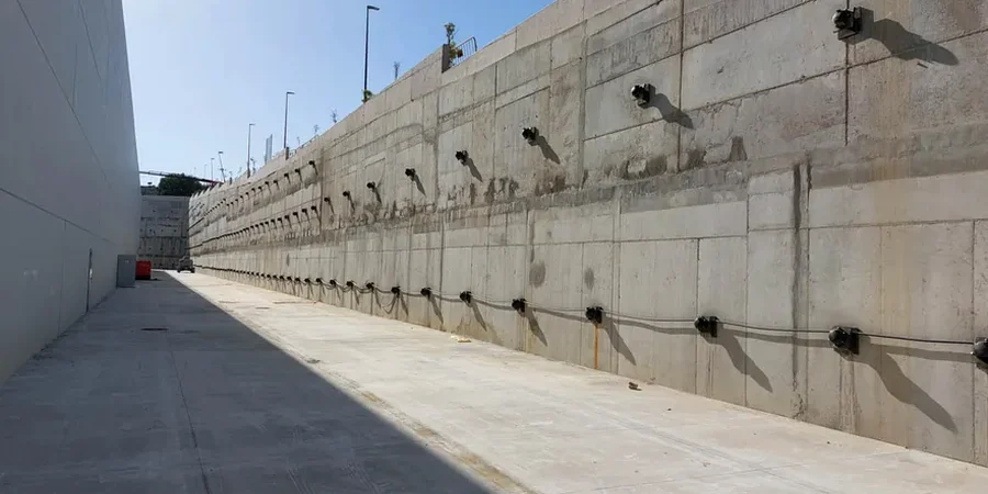
What is the difference between active and passive anchors in a shoring wall?
Active anchors are post-tensioned after grout curing to apply a predetermined load to the wall, immediately restraining lateral movement. Passive anchors are grouted bars or strands that develop resistance only when the wall moves enough to mobilize the bond stress in the fixed length. In Durham’s saprolite, passive anchors are used in the upper weathered zone where movement tolerance is higher, while active anchors control deformation in deeper excavations adjacent to existing structures or roadways.
How deep do anchors need to go in Durham’s residual soils?
The total anchor length depends on the depth of the excavation and the location of the critical failure surface. In the Piedmont saprolite profile, unbonded lengths typically extend 15 to 25 feet beyond the theoretical failure plane, while bond lengths in weathered rock range from 10 to 30 feet depending on the rock quality designation and the design load per anchor. A typical three-level anchored wall in Durham might have anchors 45 to 65 feet in total length.
What testing is required for permanent tieback anchors?
Permanent anchors require performance testing on sacrificial anchors to verify the ultimate bond stress, proof testing on every production anchor to 133 percent of the design load, and extended creep testing on a minimum of 5 percent of anchors. The acceptance criteria follow PTI DC35.1, which limits creep movement to 2 millimeters between the 1-minute and 10-minute readings at the test load. Load cells are often specified on representative anchors for long-term monitoring.
What is the typical cost range for anchor design and testing in Durham?
The engineering cost for anchor design, including submittal preparation and field testing oversight, typically ranges from US$960 to US$3,910 depending on the number of anchor rows, the complexity of the subsurface conditions, and the required testing protocol. This does not include the contractor’s drilling and installation costs, which are separate.
How does saprolite affect anchor bond stress compared to hard rock?
Saprolite in Durham is a residual material that retains the texture and structure of the parent rock but has reduced strength due to weathering. The grout-to-ground bond stress in saprolite can be 40 to 60 percent lower than in unweathered diorite or granite. Because saprolite can contain mica-rich seams and relict joints, the bond stress is often highly variable within a single borehole. Pullout tests on sacrificial anchors are essential to calibrate the design assumptions before production drilling begins.